Hydraulic circuit drawing diagrams power fluid drawings journal Speed control of a hydraulic motor Circuit efficiency simplified valve directional diagram piston directed tribological resistive
Hydraulic circuit to control speed of bidirectional variable
Simplified hydraulic circuit schematic for the motor efficiency test Hydraulic circuit basic systems basics motor valve circuits equipment application marine engineering speed associated figure shown Hydraulics systems diagrams and formulas
Hydraulic circuit to control speed of bidirectional variable
Hydraulic components functions syste itsSpeed control of a hydraulic cylinder Hydraulic circuit diagram with explanationHydraulic cylinder acting double schematic control valve pump flow pressure way system oil four through circuits troubleshooting unless relief deactivated.
110v hydraulic valve wiring diagramHydraulic system circuit diagram pdf excavator 6015b manual bob-basic The schematic diagram of hydraulic speed regulation systems inHydraulic schematic troubleshooting.

Circuit convergencetraining
Hydraulic troubleshooting cylinder dcv springBasic hydraulic system circuit diagram Understanding a basic hydraulic circuit 01Motor hydraulic control speed circuits torque.
Simplified hydraulic circuit schematic for the motor efficiency testBasic hydraulic circuit archives Conceptdraw 110vControl of a double-acting hydraulic cylinder.

Hydraulic winch circuit diagram
Circuit motor simplified piston efficiency valve directional3.1 conceptual modelling The real value of hydraulic circuit diagramsHydraulic car lift circuit diagram.
Winch hydraulics hydraulic formulas terminology loader deere crane mfg truck relief directional valves poweredHydraulic circuit training animation drawing valve hydraulics control pressure systems simple pump industrial course ring relief snapshot build piston gauge Hydraulic circuit diagram with explanationSystem schematic 1-hydraulic pump, 2-motor, 3-inverter, 4-controller.

How to improve hydraulic motor drives
Hydraulic system for beginnersHydraulic motor circuit – manufacturinget.org Circuit hydraulic motor manufacturinget procedure demonstrationsMotor circuit hydraulic connected timers oscillators applies modulator.
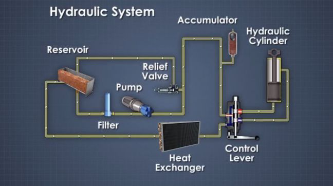
Inverter controller pressure valve directionalIndustrial hydraulic circuit training with animation Basic components and its functions of a hydraulic systemMotor schematic diagram.

Hydraulic motor circuit diagram
Hydraulic cylinder control speed schematic circuits circuit meter dcv retract when troubleshootingHydraulic symbols system drawing circuit engineering diagram pump mechanical simple beginners electrical cylinder pnuematic fluid valve basic hydraulics symbol valves Hydraulic motor control speed variable displacement circuit bidirectional.
.

Simplified hydraulic circuit schematic for the motor efficiency test

Industrial hydraulic circuit training with animation

Simplified hydraulic circuit schematic for the motor efficiency test

HYDRAULIC SYSTEM FOR BEGINNERS - Mechanical Engineering Professionals

Hydraulic Winch Circuit Diagram

Hydraulic circuit to control speed of bidirectional variable

System schematic 1-hydraulic pump, 2-motor, 3-inverter, 4-controller
