Full_wave_rectifier Full wave bridge rectifier Full wave rectifier graph
Precision full wave Rectifier Circuit Diagram | Super Circuit Diagram
Precision full wave rectifier circuit Precision full wave rectifier circuit diagram Tapped rectifier transformer coil understanding waves
Dc wave rectifier full ac 220v bridge 120hz rectification output current without rated switch use relay led noticeable flicker causes
Full-wave rectifier circuit with resistive load.Full wave rectifier schematic Full wave rectification diagramFull wave rectifier circuit working and theory.
Wave full rectifier circuit seekic diagram signal ic rectificationFull wave rectifier circuit diagram Understanding what happens in transformer with a center-tapped primaryCenter-tapped full-wave rectifier operation -….

3 phase full wave rectifier circuit diagram
Rectifier circuit diagramHalf wave and full wave precision rectifier circuit using op-amp Rectifier diode regulator electroschematicsRectifier tapped transformer typical coil tutorials happens.
Wave full rectifier circuit diagram buildRectifier breadboard demonstration solderless reduce constructed parasitic Rectifier resistive transformer kebutuhan menghitungBipolar output full wave bridge rectifier with center tapped.

Rectifier wave full center tap working circuit diagram electronics advantages disadvantages
Center tapped full wave rectifierWhat is full wave rectifier ? Rectifier tapped circuit operation circuitglobeBuild a full wave rectifier circuit diagram.
If a full wave rectifier circuit is operating from class 12 physicsRectifier wave circuit precision full diagram simple ac dc circuitsstream circuits sourced gr next Full wave rectifier schematicAc rectifier circuit diagram.

Rectifier transformer tapped output input waveform
Rectifier bridge waveform capacitor signal resistor dc circuitglobeIn-depth guide to full wave rectifier Full wave rectification diagram.
.


Precision full wave Rectifier Circuit Diagram | Super Circuit Diagram

FULL_WAVE_RECTIFIER - Basic_Circuit - Circuit Diagram - SeekIC.com

relay - Can I use a 220v AC rated switch for 220v 120Hz DC

Full-wave rectifier circuit with resistive load. | Download Scientific

What is Full Wave Rectifier ? - Circuit Diagram, Working, Advantages

3 Phase Full Wave Rectifier Circuit Diagram

In-Depth Guide to Full Wave Rectifier - Circuit Diagram, Waveform
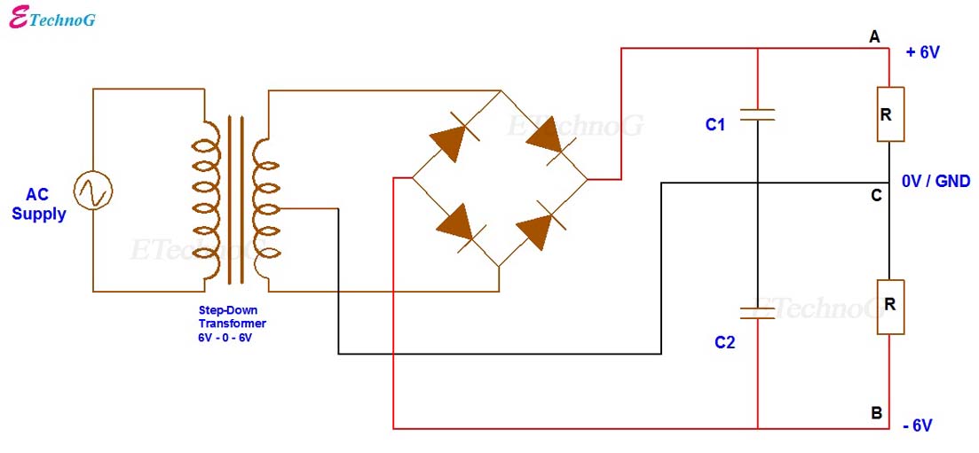
Bipolar Output Full Wave Bridge Rectifier with Center Tapped
